| cosam.org |
Power Supply Unit
The original A1200 PSU is a puny little thing which is barely able to run the computer and a hard disk. I believe it was rated at 23 watts, which just isn't going to cut it if you plan on adding many other extras.
As we're working with a PC case, it makes sense to use a regular PC PSU. There are two main flavours - the older AT models, and the newer ATX ones. Both have their own charms and annoyances:
AT PSU
Most PC stores won't stock these things as almost everything is ATX these days, but you can raid one from an old PC. You'll know that you have an AT PSU if it has two flat, 6-pin motherboard power connectors marked as P8 and P9. Many also have a long, thick cable with the power switch on the end.
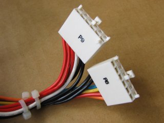 AT PSU motherboard connectors | 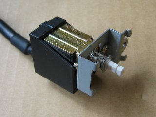 AT PSU power switch with cable |
Electrically, the AT PSU is easier to hook up and it simply switches on and off with a toggle switch. The main problem you'll come across when using an ATX case (which have power push buttons built in) is getting that great lump of a power switch mounted inside.
I finally opted for this kind of PSU from my tower, as I had one lying around and found that it would fit my chosen case without too much hassle.
ATX PSU
These are by far the most abundant PSUs at the moment as they're used in pretty much all new PCs. They have a larger motherboard connector than AT models consisting of two rows of holes and usually a tab on one side.
Unlike AT PSUs, ATX models have no external power switch as they are designed to be able to be operated by software, like when you shut down a PC using only the mouse. This makes them a little harder to work with than their older AT brothers.
To switch on an ATX PSU, it's necessary to bring the (active low) PSON line down to ground (zero volts). The simplest way to do this is to physically connect the PSON wire to a ground wire, which is an adequate solution if your PSU has a switch mounted on the back. Alternatively, if you can fit a toggle switch to your case, you can use this to connect the two lines. If you want to use the power button of an ATX case, you'll need to rig up a small circuit to make it act as a toggle switch.
Wiring Up
Whichever way you go, there is some common ground you'll need to cover. As these things are made for PCs, you're unlikely to find a nicely fitted 5-pin connector for your Amiga hanging out of it. The easiest way to sort this out is to fit the connector from an Amiga PSU. This can be wired up to the main bundle of wires comming out of the new PSU. On AT models, this is the one with the P8 and P9 connectors, on ATX versions it's the one with the large, double-row connector. Unfortunately, the other connectors (such as those for hard disks, floppy drives, etc.) can't be used on their own as they have no -12V line.
Make sure you cut off enough cable along with the connector, depending on how you're planning to wire it up (see later). I also trimmed a bit of rubber off the back of the plug for a bit more flexibility, which turned out unnecessary in the end. You'll only need to connect four wires, as one is for the shield around the cable. It won't be a problem if you connect this to ground, but I understand that shields generally work better when grounded at one end only, so I simply snipped off the bare wire. Commodore, in their infinite wisdom, apparently never set a colour coding standard, so you'll have to check which pin is which with a multimeter or test lamp.
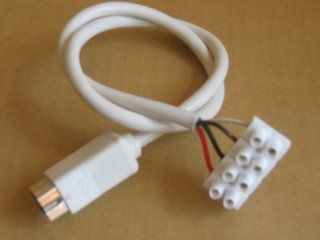 Trimmed Amiga 5-pin power connector with connector block attached. | 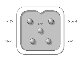 Pin-out of the connector (on the end of cable, not on the back of the Amiga!). |
The simplest and safest way to wire it all up is to use a regular connector block to join the wires from the PSU to those of the original 5-pin plug. Simply strip back the plastic and screw the PSU end into the top and the Amiga end into the bottom. If you want to keep hold of the original AT/ATX connector, you can screw the wires from that in too. I was however looking for a neater solution, so I wanted to connect things up inside the PSU itself.
Caution - Danger of electrocution! Before opening anything up, be aware that a PC power supply can store a dangerous charge in its capacitors for several days after it's been switched off! You shouldn't need to go anywhere near the dangerous parts, but you should make sure everything is discharged before starting. If you're in any way unsure, consult an electrician or use the external connector block approach above. |
Anyway, if you're planning on making internal connections, and you're confident you're not going to fry yourself, open up the PSU case and have a look what you've got. If you're using an old one, now's a good time for a bit of spring cleaning as these things get incredibly dusty over time. An old toothbrush is good for getting that gunk off of the fan.
Locate your main bundle of wires and trace them back to the PCB inside the PSU. If you were planning on cutting off the original connector(s), go ahead and do so, but leave about 10cm of wire at the other end (inside the PSU itself). However, if you want to keep the plug(s), you may want to keep a few wires intact to avoid having too large a connector block inside the PSU.
In any case, you should now have a whole bunch of short red and black wires inside the PSU, which are your +5V and ground connections respectively. You'll also need the +12V and -12V connections, which are yellow and blue respectively. These can be connected up to one end of a connector block - I had four red and four black wires, which I twisted together into bundles of the same colour and screwed into the connector block to keep things neat. You may want to use less and either cut off or insulate the rest.
Cut off the Amiga connector with a good length of cable. If you're not sure how much to cut off, take a length approximately equal to the diagonal of the side of your case to be sure. Strip back the plastic and connect the wires up to the other end of the connector block inside your PSU. If you're keeping the original plugs, you may need to connect their wires back in the same holes.
If you're using an ATX PSU, you way want to attach some extra wires to the PSON and permanent +5V lines to rig up a power switch later. Note that the permanent +5V is not the same as the regular +5V! As the name suggests, it is on even when the computer is off, so this is what you'll need to use to power the on/off switch circuitry. The rest of the lines you'll be able to figure out for yourself.
When everything's connected up, it's time to check that your cables still fit in that hole in the PSU case, and modify it as necessary. This isn't likely to be a problem if you removed the original power connectors, as the new cable is likely to be thinner than the original bundle. In this case, you'll probably need to secure the cables on the inside of the unit with cable clamp or nylon tie-wrap.
I'm not too sure which wires are left over from an ATX PSU, but for AT models, you'll have an orange "power good" and a white -5V left. I left about 10cm of each and insulated the ends in case I ever need them. You can of course snip them off flush with the PCB if you're sure you don't want them, just don't leave any bare ends which could come in contact with other wires or the metal casing.
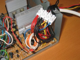 The inside of my AT PSU. | 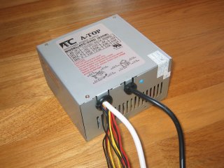 The finished, modified PSU |
Fitting an AT PSU
Mounting the PSU itself is a trivial task with most cases. The only problem I came across was getting the power switch mounted in a position it would fit and work properly.
Luckily, my case had an easily removable power button and holes for mounting an AT toggle switch. I did however need to bend the spade connectors slightly to fit around the reset switch below. With the switch in place, I was left with two problems: Firstly, the "stick" controlling the switch was much longer than the original, and secondly, it seemed to require a little more travel to work correctly.
Thankfully, the original power button did provide adequate travel, so this was no longer an issue. The obvious solution to the first problem was to hack the end off the switch's stick, which helped but still left me with an excess. I therefore modified the power switch push-rod by cutting it right back to the flange around it. I knew this would be too short but, as it's hollow, I was able to put a small screw into the end of it to allow for some fine adjustment. At my first attempt, the push-rod was still too short and therefore couldn't move the switch far enough to make a difference. After one small adjustment by turning the screw, it worked perfectly.
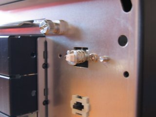 Here's the switch after hacking a good few millimetres off the stick. | 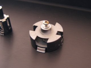 The button in the front panel of the case, with adjusting screw fitted. |
Next: Mounting the Motherboard >>
![]()
![]()
![]()
![]()