| cosam.org |
Port Access
Depending on how you mounted your motherboard, you may be left with all the ports along (what was) the rear of the machine inside the case. This is fine if you don't mind having cables running through the back of the tower and opening the case every time you want to connect something, but most people will want something a little more practical.
D-Connectors
The obvious answer is to make extension cables for the ports you want to use and mount connectors in the case. You can make these easily and to the exact length you need from very cheap parts. Aside from a good length of ribbon cable, you'll need some sub-D connectors to fit the ports you want to extend. If you suck at soldering, or are just plain lazy, the crimp-on type are great. You simply lay the ribbon cable over the teeth, clip on the back and squeeze. If you like soldering, you can get the cheaper solder-on type, although by the time you're done, you'll probably not be as keen on soldering as before.
I found a happy medium by raiding some old PCs for parts. Many PCs, especially older AT models, use ribbon cables to connect headers on the motherboard to ports which are mounted on the back of the machine. Better yet, they have neat little black caps to cover the solder work and brackets for mounting the connectors in the spaces for expansion slots. This was a great find as half the job was done for me already!
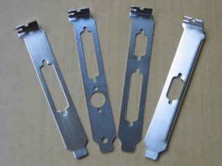 A selection of mounting brackets for various ports. | 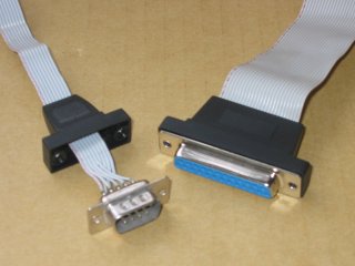 These caps nicely cover the soldering. |
An easy way to handle the 23-pin ports (for a monitor and external floppy drive) is to leave them unconnected. I don't even have a proper Amiga monitor (I use an internal scan doubler/flicker fixer to connect to a VGA monitor) and if I need a second floppy I'll connect it internally. If you do need to make extension cables, finding the connectors may be difficult, although there are specialist Amiga retailers who still stock such items.
The 9-pin pre-made cables I salvaged were a little short for my needs, but I still recycled their connectors - it's easy enough to desolder so few pins, but I wouldn't want to do the same with a 25-pin parallel connector... A bit of stripped and tinned ribbon cable was used to connect this to a new connector at the other end. Unfortunately there was only space for a cap on one end - the ports on the motherboard come rather close to the 5.25" bays of the case. A crimp-on type connector would have been better here. If your motherboard has a removable mouse port on an extra board or just a cable, you may want to connect directly to the header for this.
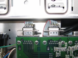 The connectors just fit in the case. |
To connect up the serial and parallel ports, I used the pre-made PC cables and added an extra cap from a similar cable before soldering on a new connector. If you like, and you know the pin-outs, you could always use a 9-pin connector for the serial port. Unfortunately, the screws for the caps I had were slightly different to the original A1200 screws for the ports, so I couldn't screw the two together easily. This shouldn't be too much of a problem though as there's little chance of these cables being tugged out.
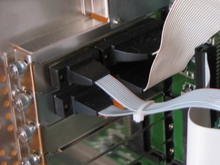 The inside of the case is just full of cables... | 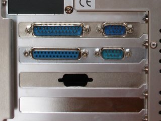 ...but everything's nice and neat on the back. |
Rear Panel
I thought it'd be nice to group together the stereo and composite video connectors on the back of the machine, but I also wanted to provide a 3.5mm jack so that headphones or PC speakers could also be directly connected. As these are all simple round connectors, fabricating a mounting panel for them which fits in the gap in the back of the case isn't too hard, although the layout is a little limited by the power cable behind it in my case.
The rear panel itself was cut out from the casing of an old CD-ROM drive, but you could of course use any reasonably thin metal plate. I then drilled out the holes necessary for the RCA connectors and 3.5mm jack, and a few more to mount the keyboard socket. It's important to clamp such a thin plate down well before drilling - on the first hole the drill bit tore the metal up rather viciously. I was able to hammer out most of the damage, the rest of which is covered by the connector anyway. Phew! If you end up with not-quite-round holes, a quick whiz with a countersink bit will finish them off nicely.
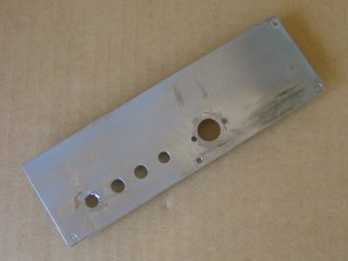 The rear panel before painting. | 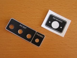 Some stickers to show what's what. |
As you can see from the pictures, my attempt at polishing up the plate didn't really work out, so I decided to spray it up matt black like the rest of the case. I made a couple of stickers to add some legend text to the panel and stuck these on before applying the last couple of top coats, which will hopefully keep everything in place. Cutting the stickers leaves a very white edge, which I went over with a black marker before putting them in place. I also gave the jack's mounting nut a quick lick of green model paint, which I believe is the standard colour code for these things.
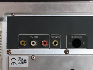 The finished panel, with some connectors mounted. |
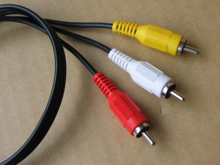
With the plate finished, I could start wiring up the connectors. I found out the hard way that soldering up the cables before mounting this kind of RCA connector makes the job kind of impossible. All these connectors are simply screwed into place in the panel and wired up to an off-cut of a pre-made A/V cable with moulded plugs. The stereo jack is connected up to the centre pins of the red and white RCA sockets, and of course a common ground (the separate gound wires and probably overkill, but I wanted to ensure a good connection). I've no idea which contacts of the jack connect to where; I used an 3.5mm to stereo RCA adapter cable to figure out the connections.
 These cables give a neat result. | 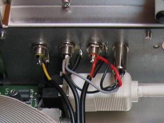 The wiring on the back of the panel. |
The finished rear panel was easy to mount in the back of the empty motherboard tray. Due to physical restrictions inside the case, the panel is held in place with four screws in an L-shaped configuration, so two of the edges have an extra 5mm tagged on to take the screws. The other two edges have an extra 2mm to avoid leaving a gap between the panel and the case. All mounting holes are 3mm and the hard disk screws supplied with the case fitted a treat.
Next: Floppy Drive >>
![]()
![]()
![]()
![]()