| cosam.org |
Interface Circuits
AT/A1200
The simplicity of the AT power supply makes hooking things up very easy. All we really need is a few resistors for the LEDs, which you could always just solder into the existing wires. I however went for the more modular approach and built a tiny circuit board to connect up the motherboard to the case's LEDs and also the reset switch.
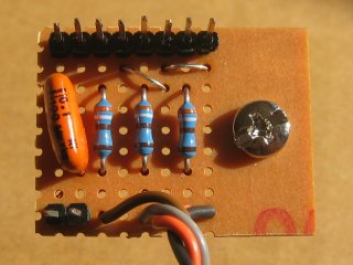 The AT interface circuit is very simple. | 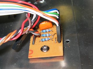 Here it is mounted in the case. |
The main function of the circuit is to connect things together. The four coloured wires lead to a plug which fits on the A1200's LED header. At the opposite end, three pairs of header pins are mounted in order to connect the LEDs in the case. The remaining pins are used to connect the reset switch and are stradled by a big fat capacitor (I'm not sure if this helps at all, but it seemed like a good plan). With a spacer and some insulation underneath, this board is small enough to be mounted almost anywhere in the case with just one screw.
The LED pins aren't actually in exactly the right place - most cases have a connector which fits over three pins, instead of two. However, the metal contacts inside the connector are easily moved, so the LED can still be connected to a 2-pin header (as long as it's unobstructed at one end). If I were to make another board, I'd probably install a 3-pin header, or at least leave a gap between the pins.
ATX/A1200
As there are several small circuits involved for interfacing the A1200 to the ATX power supply, switches and LEDs, I thought it'd be nice to build one circuit board with all the electronics on it.
The board features a header to connect the A1200's LED header, via resistors, to the LEDs on the case and a simple capacitor for the reset button which connects to the test pads as previously explained. The most complex circuit is that for the use of the case's power button. This involves a debouncing circuit using a schmitt trigger which connects to a D-type flip-flop which provides the toggle effect.
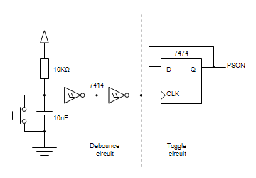 Circuit diagram for connecting the power switch. |
I built the whole thing on a small piece of stripboard into which I drilled a few holes to mount it inside the case. Below is a picture of the finished board, which looks slightly different to the layout diagram as I had to make a few "minor adjustments" along the way.
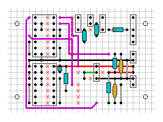 The stripboard layout of the circuit. | 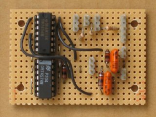 The finished board. |
I didn't want to have to solder any wires to the motherboard, or to my new circuit board, so I did it all using headers and connectors. This is especially handy for connecting up the LEDs and switches in the case, as they all have this kind of connector. It also means that if I ever need to replace anything, it's simply a matter of unplugging the part in question and fitting a new one. The extra cables are easy enough to make from regular wire and some clip-together or pre-fitted plugs.
Next: Finishing Touches >>
![]()
![]()
![]()
![]()