| cosam.org |
Construction
Overview
The main "chassis" of the system is a simple plank of wood measuring about 40cm x 25cm (16" x 10"). The basic parts of the system are then screwed onto this using self-tappers. The power supply and 3.5" disk drive cage were raided from a couple of old PCs, as was the mount for the serial port on the front.
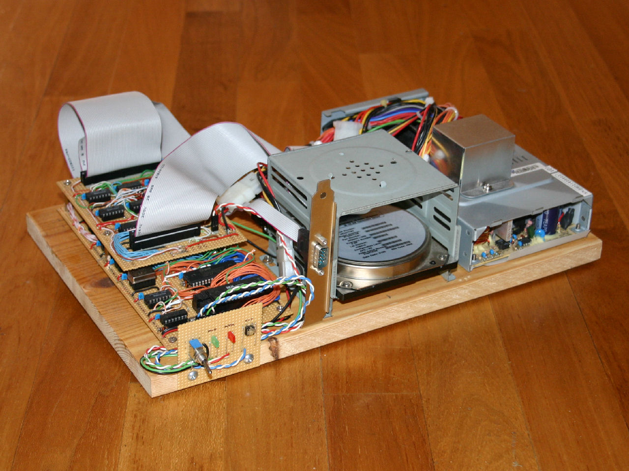 The Z80 computer viewed from the front (click for a larger version). | 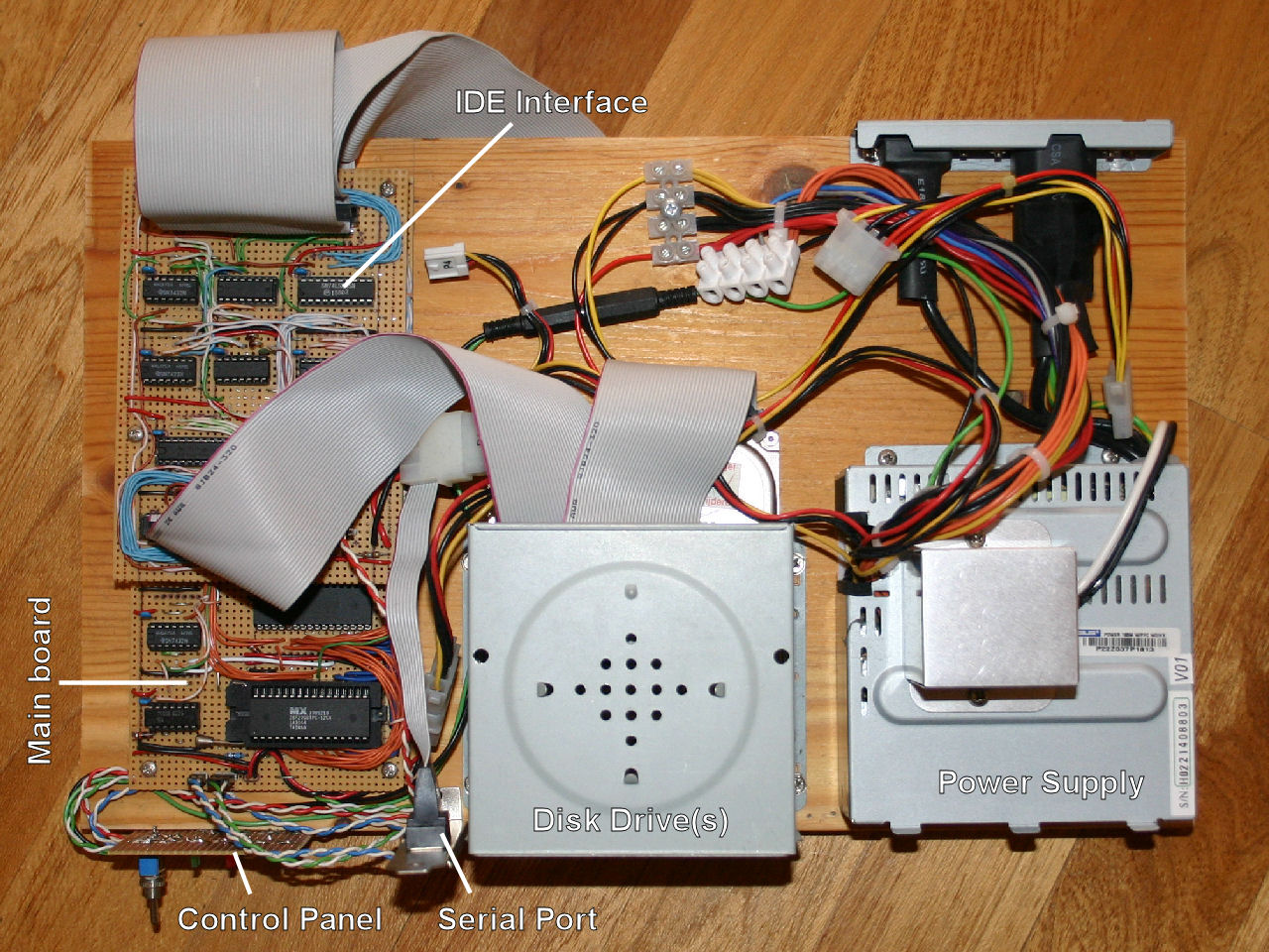 Top view, with various parts of the system labeled. |
Circuit boards
Both the main board and the IDE interface were built on as wide a piece of stripboard I could find. These are mounted to the "chassis" using the sort of stand-offs used to mount PC motherboards in their cases, insulated where they make contact with the copper conductors of the stripboard using small plastic washers.
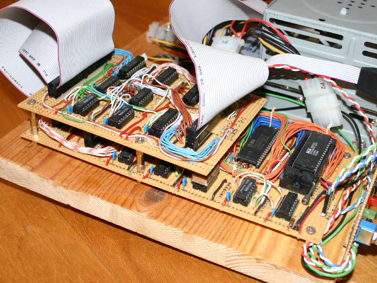 Close up of the main board (below) and IDE interface board. | 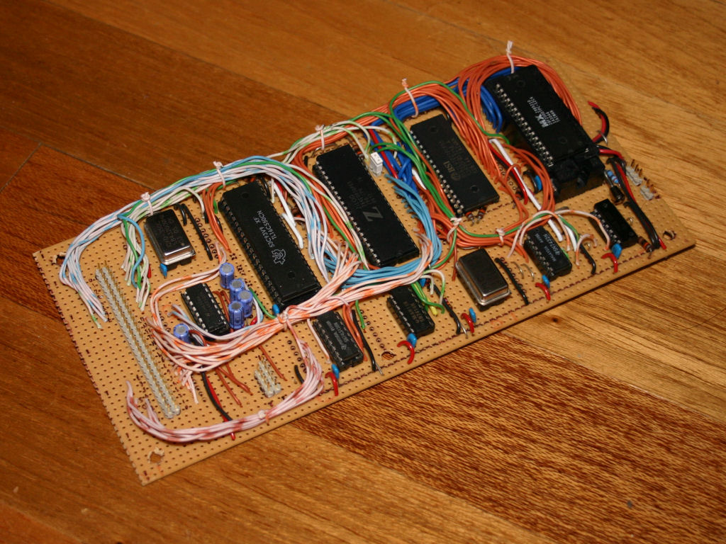 Main board. |
The main board is a complete system in itself, including CPU, memory (ROM and RAM) and the serial I/O system. The ROM (located far right on the above photo) is actually an old PC Flash BIOS chip, fitted using a ZIF socket so it can be eaisly removed for reprogramming. Each board has a 50-pin header which implements a simple expansion bus. A good old 50-pin SCSI ribbon cable can therefore be used to link the individual boards together.
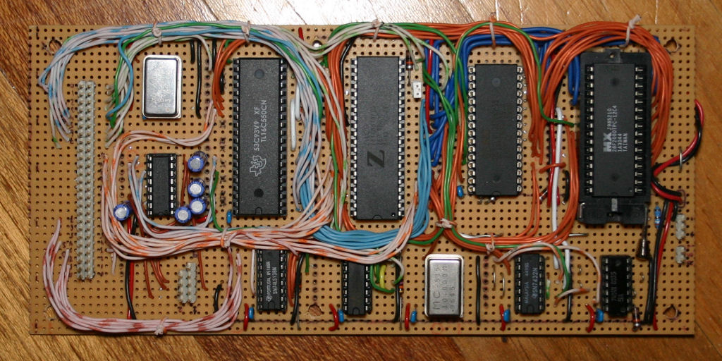 Main board from above. |
For most of the wiring I used solid-core CAT-5 network cable. Not only is this nice and thin, which was important for the bundles of wires making up parts of the address and data buses, but you also get 8 different colours. You don't however get red or black, so the power and ground connections are made from regular insulated link-up wire.
Control Panel
Before the proper front panel was built, I made this simple control panel to mount the power and reset switches and a couple of LEDs. The thinner wires running off to the left terminate in two-pin header connectors and plug into the ciruit boards. The power switch's wires are connected to the Ground and PSON lines of the ATX power supply via another simple connector.
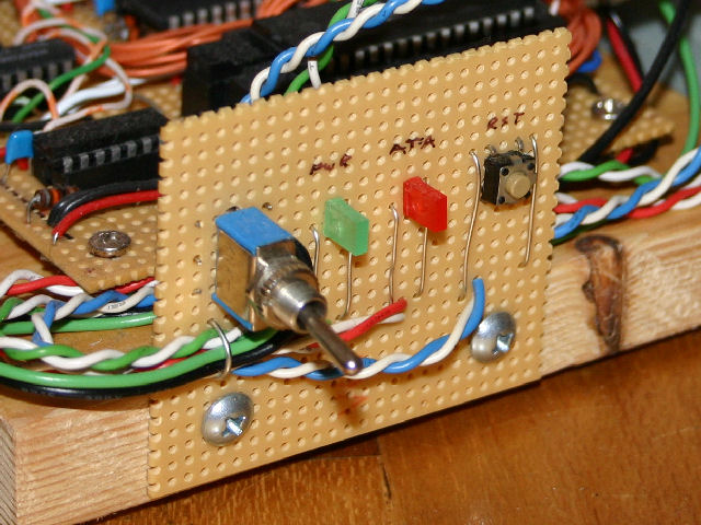 The system's control panel featuring power and reset switches and indicator LEDs. |
Construction Tips
IC Sockets and Stripboard
Soldering in IC sockets before making any track breaks can help out when testing the circuits. Opposite pins of the sockets will be connected if the joints are good, and short circuits between tracks are easy to test for. After making the breaks, you can test they are clean by doing the same test again.
Soldering Ribbon Cable
Don't just cut bits of ribbon cable straight - check what kind of position it has to fit in and adjust your angle of cuttage accorindly. Even ribbon cable being soldered in a straight row of stripboard holes will generally need longer wires at the outer end than in the middle.
![]()
![]()
![]()
![]()