| cosam.org |
Initial Start-up
Although the front panel features a light which indicates whether the voltages are good, I checked these on the terminals to the side of the PSU with a multimeter before inserting any cards into the backplane.
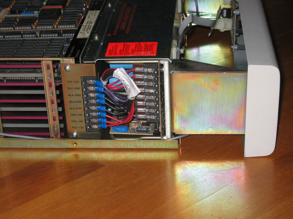 The terminals here can be used to verify the voltages are within tolerances. | 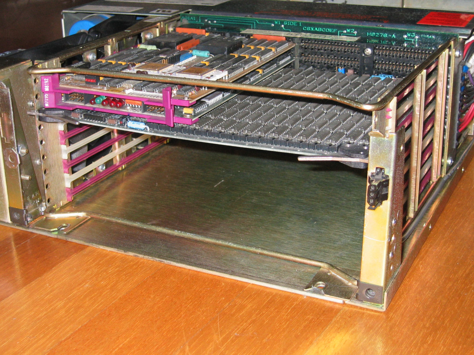 The backplane with processor, MXV11-B and NSC memory board installed. |
The next step was to plug in the processor card and the MXV11-B, which
can be used to hook up the console. The latter has plenty of jumpers
which I needed to check before fitting, using
a scanned copy
of the user guide ![]()
![]() I found on the Internet. I set the card up to
function as the console and checked the rest of the jumpers. From a couple
of wire wraps, I could see the board was configured for the MXV11-B2 ROMS.
I found on the Internet. I set the card up to
function as the console and checked the rest of the jumpers. From a couple
of wire wraps, I could see the board was configured for the MXV11-B2 ROMS.
Next I needed to arrange the console itself, for which I used a PC and terminal emulator software, set to 9600/8/1/N with DSR/DTR. In order to interface the PC's 9-pin serial port to the MXV11-B I used a 9-pin RS-232 null modem cable linked to the D315 panel which came with the system using a 9-to-25 pin adapter. The D315 has a ribbon cable with two AMP plugs which plug into the SLU ports of the MXV11-B. For the console you need SLU-1 which is located to the right when viewed from the back of the mounting box.
With eveything connected I plugged in the power cord and flipped the chunky power switch on the back of the BA11-S to the "1" position. The fans spun up, but nothing was to be seen on the console. Fiddling with the HALT and RESTART switches showed that something was happening as the RUN light would light up when it should. But no, even with a few choice keypresses, the console remained lifeless. Nevermind, I thought, it was time I turned in for the night anyway.
The next day I went over all the jumper settings by starting from the "as-shipped" configuration in the manual and following the rather handy flowchart to alter things as necessary. When I wasn't sure which option I needed, it was possible to tell from a combination of the original jumper settings, the invaluable manual and a bit of experimentation which jumpers needed to be open or closed. I also went over the cabling: there are two sockets in the MXV11-B and two plugs which go into these. On the D315 there are also two sockets, so I double checked which connected to where and was reasonably sure I had the PC connected to SLU-1. Time to try again...
It was well worth checking that wiring; I was immediately greeted with:
173000
@
Not exactly what you'd call verbose output, but it was proof I had things connected up correctly. The "@" is the prompt of the ODT (On-line or Octal Debugging Technique) firmware which basically does what the older PDP-11 front panels did, allowing you to manipulate memory and perform other simple tasks. As the front panel was still set to HALT the system had gone straight into ODT mode and was waiting for input. I experimented with a few commands before moving on to the next step.
The MXV11-B module contains the MXV11-B2 boot ROMS which have bootstrap
code for several popular devices (including the RL02) and, interestingly,
some simple diagnostic programs. I was eager to get the ROMS running in
order to run some of the tests, so it was back to the manual. However, it
turned out I needed the manual for the KDJ11-A processor
[available from Bitsavers ![]() -
please use a nearby mirror]
and not that of the MXV11-B itself. As it turns out, the ROMS were probably
doing their stuff the very first time I fired up the system!
-
please use a nearby mirror]
and not that of the MXV11-B itself. As it turns out, the ROMS were probably
doing their stuff the very first time I fired up the system!
When the system is started (and, of course, not on HALT) the ROM code first runs a memory test and then starts looking for boot devices. These routines only produce output when something significant happens and, seeing as the memory checked out OK and there weren't any storage devices present, nothing was output to the console. In order to get to a manual prompt you either need to a) wait for the whole lot to time out, or b) hit CTRL-C to break the program. Being an impatient type, I hit CTRL-C for all it was worth. After a few presses, the screen looked like this:
173000
@BOOT>
Good stuff! This is the prompt of the boot loader program which is also home to the built-in diagnostics (for full-on diagnostics, you need to boot the XXDP diagnostic system, which of course requires working storage and the appropriate software). If you type anything wrong here, the system is kind enough to tell you to type "HE" for help. You are then presented with a whole bunch of options:
MXV11-B2 Y3.0
General syntax is
[CSR] command [UNIT]
[CSR] is optional (octal) - see manual for default
[UNIT] is optional (octal) - 0 is default
Command is one of -
DL - boot RL01 or RL02 DY - boot RX02
DX - boot RX01 MS - boot TSV05
DU - boot MSCP NP - boot DECnet via DPV11
NU - boot DECnet via DUV11 NE - boot DECnet via DLV11-E
NF - boot DECnet via DLV11-F DD - boot TU58
TM - test memory CL - clock on or off
MP - show memory map IN - initialize bus
LD - load boot block "/" - examine or deposit memory
TS - Serial line test TF - Floating point test
TC - clock test
BOOT>
Cool stuff indeed. The bottom section refers to the built-in diagnostic tools, of which I tried a few. Most of them produce no output unless something goes wrong, so they're generally not all that exciting. The exception is the "MP" command which dumps the memory map, like this:
BOOT> MP
CPU OPTIONS
Processor Type = 5
Floating Point Instruction Set
Type Control C to Quit
MEMORY
Starting Ending Length
Address Address in words
00000000 - 17277776 07540000
I/O
Starting Ending Length
Address Address in words
17765000 - 17765776 00000400
17772102 - 17772102 00000001
17772200 - 17772376 00000100
17772516 - 17772516 00000001
17773000 - 17773776 00000400
17776500 - 17776506 00000004
17777520 - 17777520 00000001
17777524 - 17777524 00000001
17777546 - 17777546 00000001
17777560 - 17777566 00000004
17777572 - 17777676 00000043
17777744 - 17777752 00000004
17777766 - 17777766 00000001
17777772 - 17777772 00000001
17777776 - 17777776 00000001
BOOT>
This is the output after inserting the National Semiconductor memory card. Under "Length in words" you can read off the total amount of memory in the system. This is of course an octal value indicating the number of 16-bit words available so you'll need to double it to get the total number of bytes. In this case, we're just shy of 4MB.
![]()
![]()
![]()
![]()