| cosam.org |
Fixing Horizontal Distortion
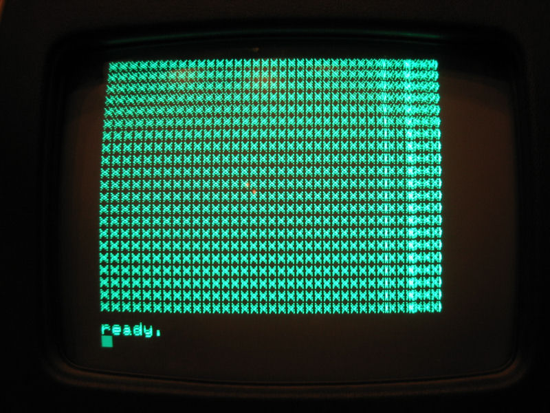
Even though the wavy picture was cured, there was still some distortion in the image. As was visible on this photo, there was one narrow column towards the right of the display and the last few characters on each row were "doubled back" on their predecessors.
Looking at the waveform of test point 13 on the schematic revealed a problem with the horizontal drive circuit. The large "M" part looked correct, but the two smaller peaks preceding this weren't meant to be there. They also seemed to correspond to the problem areas of the screen, i.e. a small disturbance about three quarters on the way through and a larger blip towards the end.
Not knowing much about diagnosing CRT problems, I again turned to the
guys at the
Vintage Computer Forums ![]() for suggestions. Working back through the circuit revealed that the
incoming signal from the main board wasn't quite right, so maybe the
bad regulator was all that was actually wrong with the video board.
for suggestions. Working back through the circuit revealed that the
incoming signal from the main board wasn't quite right, so maybe the
bad regulator was all that was actually wrong with the video board.
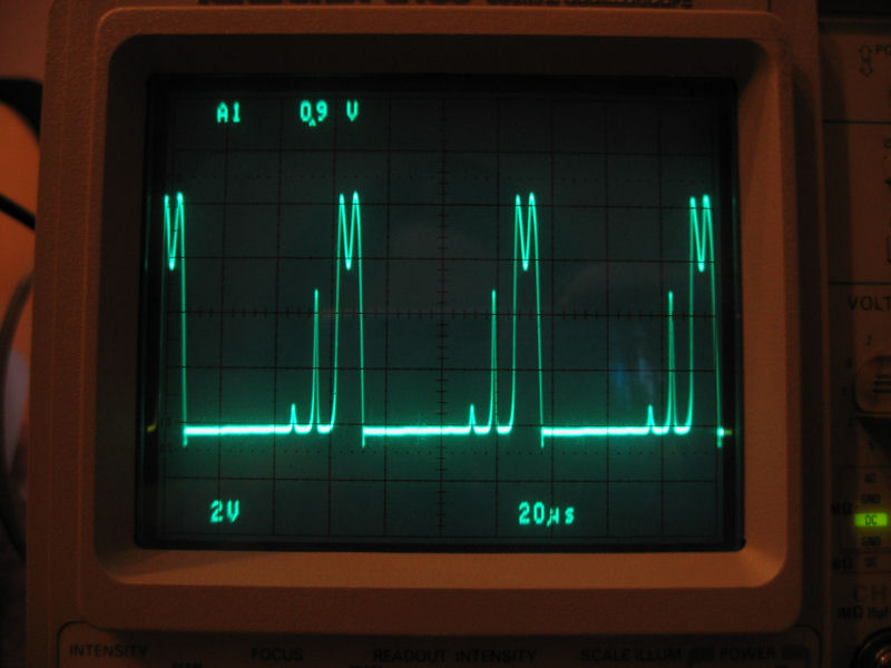 Waveform at test point 13, showing two extra peaks. | 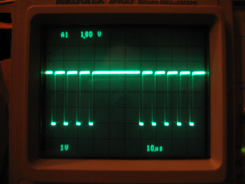 Incoming signal from the main board was off. |
Back in the realm of things I understood, and with a good tip from a forum member, I set to figuring why the horizontal signal was wrong at the source. Turns out that the flip-flop which provides this signal, which was one of the socketed replacement ICs, was missing a connection which left one of its inputs floating. A bit of wire-wrap wire across the offending pins was enough to put the signal right, and the display looked almost right again. All that was required now was to centre the picture on the screen, which is done by twiddling two metal rings on the neck of the CRT.
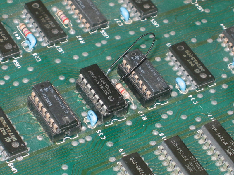 Temporary jumper confirmed which pins needed soldering. | 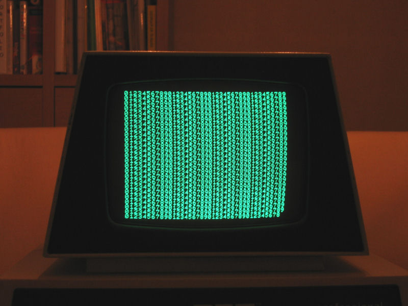 A quick BASIC test program to help center the screen. Done! |
So, finally, a steady image with all characters present and correct!
Next: Making Tapes >>
![]()
![]()
![]()
![]()