| cosam.org |
PCB Repair
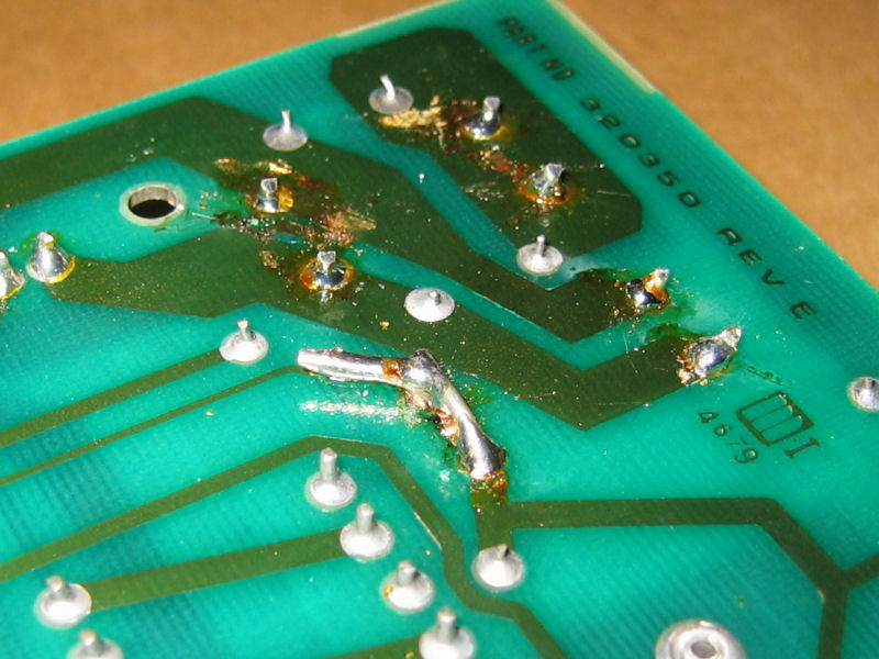
In order to repair the PCB, I tracked down some self-adhesive copper which I could cut into shape and solder onto the damaged areas. Most of the patches were simple strips, but the large section for the rectifier diodes needed a bit more fettling. The recess in the solder mask was deep enough to get a rubbing of the shape on a piece of paper using a soft pencil. Using this shape as a template, I prepared the replacement section and removed a few millemeters of adhesive where it was to be soldered to the remaining traces.
I thought it'd be nice to re-coat the new copper with solder mask to protect it and somewhat blend the reparied section in with the rest of the board. Searching for a brush-on replacement led nowhere, but I found this transparent green paint which is sold for colouring light bulbs. It's therefore quite resistant to heat and, although a little darker, it's almost the right colour.
 New section of PCB trace, lap-soldered in. | 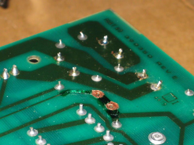 This paint almost passes for solder mask |
With the new section in place, I refitted the diodes and soldered them in. The result isn't exactly beautiful, but it looks a lot better than it did!
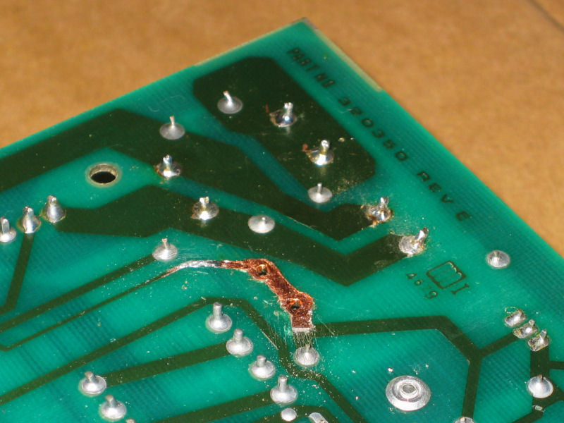
 Before... | 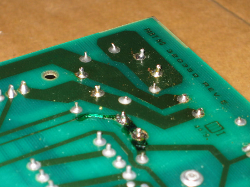 ...and after. |
I put the board back in the case and powered up to see if anything had changed. The characteristic garbage screen appeared, then it went blank as before. But then something unexpected appeared - the BASIC banner and prompt! I've no idea what the problem was, but apparently something I'd done had got her running again. Great progress, but it wasn't quite over just yet...
Next: Display Problems >>
![]()
![]()
![]()
![]()