| cosam.org |
Homemade Dew Heater
Design
A dew heater is based on a very simple concept - send a current through something that has resistance and heat is produced. Given the simplicity, I figured that the commercially available solutions to this were generally rather expensive for what they are. After a quick surf, I found plenty of information on building a homebrew dew heater, so I designed my own.
One of the main problems I had with most of the commercially available heaters was the use of a switching power supply. These systems are based on a (potentially) high-power heater, the output of which is controlled by switching the current on and off. This can lead to irregularities in the power source which isn't too good for sensitive equipment (such as computer controlled telescopes) using the same power supply.
However, it's of course a good thing to have some control over the output of your heater. The idea is to provide just enough heat to prevent dew from forming - any excess heat will cause disturbance in the air in front of the scope, which will eventually affect image quality. The solution was to build a heater which was itself made up of several heaters, each of which could be individually switched on or off.
For the low power levels I was looking for, Nichrome wire wasn't really an option as I'd require such long lengths to get the required resistance. Many designs use several "packs" of resistors connected in parallel, with these packs connected together in series to provide the resistance required. However, putting several such heaters in one strip isn't exactly practical, and the wiring could become a real nightmare. Other designs, for use with switched power controllers, put all the resistors in parallel (an arrangement like a ladder), which would create too much heat if left on constantly.
My solution was to use several "ladders" of parallel resistors, but with resistors of a higher resistance, resulting in less heat output. One end of all the resitors is connected to a common wire, then separate wires to connect the other ends of resistors of the same value. The result is three individually controlled parallel arrays.
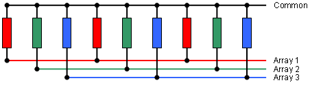
My research told me that I'd need around 3-5 Watts of power to prevent dew from forming on my LX90's 8" corrector plate. I also wanted that all-important fine control which would allow me to tailor the heat output to the conditions. The power outputs of the individual heaters are therefore 1, 2 and 4 Watts. By turning these on or off, this gives a range of 0-7 Watts, in 1 Watt increments. Depending on your requirements, you may want to add (or replace other heaters with) an 8 or 16 Watt heater. For smaller scopes, you may even want a 1/2 Watt element, to give some really fine control.
Calculating the resistance required to provide a certain level of output isn't too hard. There are two basic equations in play:
- Ohm's law: E = I x R, which states that voltage (E) is equal to current (I) multiplied by the resistance (R).
- Resistance is equal to the square of the voltage, divided by the power (in Watts). Or: R = E2 / P.
Using a spreadsheet I made the following table to calculate the values of parts I'd need. Voltage is based on my power supply, which outputs 13.5V. There are 15 resistors per element, a total of 45 for all three. These figures will depend on the diameter of the telescope for which you're building the heater. The more resistors your have, the closer together they'll be, resulting in more even heat distribution.
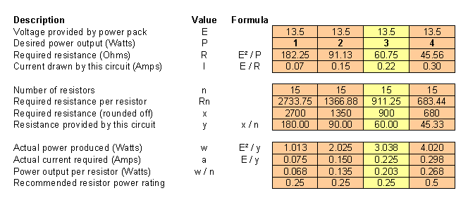
The required resistance is calculated and multiplied by the number of resistors in one heater. This is because the resistance of a parallel array of resistors is equal to that of one resistor, divided by the number of resistors in the array. This value is then rounded off to a value which is readily available. The whole calculation is then reversed with this rounded value to give the actual figures for a heater based made with these parts. As you can see, the power output is very close to the original desired value. In practise, this is of course never so exact, due to the slight differences in the individual resistors.
The amount of power output per resistor is an important figure - resistors are rated based on the amount of power they can output safely. I've rounded up the values to the nearest quarter of a Watt to provide a recommended minimum rating. Higher ratings are of course fine, but the parts will tend to be physically larger. It's of course aesthetically pleasing if your resistors are of approximately the same size, but they'll all be covered up later anyway.
Another important consideration is the amount of current the heater will draw. Add up the number of amps the heater will draw, and put a suitable fuse (i.e. one with a slightly higher value than the total current required) in the circuit.
Construction
Heater Elements
Before starting, figure out exactly how long your heater strip should be. Substract a couple of centimeters for attaching cables, then divide it by the total number of resistors to calculate the required spacing.
You'll need several lengths of bare wire, the gauge of which will depend on the current your heater will draw - 18 AWG is generally fine for this purpose. Remember that the common wire is shared by all heater circuits, so it must be able to take the full current of all elements combined. You may get away with slightly thinner wire for the individual elements. I used stranded wire for extra flexibility so that the strip can be removed and rolled up for storage without too much stress. Solid wire is easier to work with though, and may be more suitable if you intend to install the heater permanantly.
If you can find a length of uninsulated, twisted, stranded wire, you'll save yourself a lot of work and frustration - removing the insulation from stranded wire and twisting it yourself is a lot more work than you'd think! Stripping all the insulation off at once, or twisting the strands as you go, tends to leave you with an unusable, tangled mess. My technique was to strip half the wire, a few centimeters at a time. I pulled the last few centimenters I stripped to the end of the wire, but left it holding the strands together. You can then clamp this end in a vice and twist up that half of the wire. Tinning the wire at regular intervals will help keep it together and allow you to repeat the process on the other half of the wire without unwinding it all again.
The common wire is on its own and therefore need not be insulated. The rest, however, are crossed regularly by the legs of resistors and will probably be quite close to eachother. It's therefore necessary to insulate the areas where the individual heating elements could make contact with eachother. This can be done by placing insulation tubing on the legs of the resistors, but I figured that, as the wires are so close to each other, I'd be better off insulating those instead.
The basic wiring and spacing of the components can be greatly simplified by fixing the common wire in place and marking the positions of the resistors on a strip of paper next to it. Another option is to make a sort of jig out of cardboard with slots in the appropriate places, placing the resistors in the slots and then soldering the wires in place.
It's a good idea to regularly check the resistance of the heater elements (and for shorts) to limit the location of any errors to a few resistors. If you wait until after soldering all those things in place, troubleshooting will be far more difficult. When checking for shorts remember that, due to the common wire, there will be some measurable resistance between the wires for each array! I pulled a working heater apart because I found such resistance between the elements, only to realise the error of my ways when I sat down and thought about it logically... When you're all done, do a final check before proceding.
To connect the heater elements, solder an appropriately thick cable to the common wire and each of the elements. Four-core wire is of course perfect for this, just make sure it's thick enough to carry the required current. The other end can be terminated with a four-pin connector of some type, but again, make sure it's up to the job.
Covering
Without covering the heater, a great deal of the heat produced will radiate off into the air, which is obviously a waste of your precious energy. A covered heater will not only be better protected, it's also going to look an order of magnitude better than a strip of wires and resistors! The basic idea is to provide a thin layer of material on the side which will interface with the OTA, and insulate the other side to prevent wasting all that heat.
Looking at the designs I've seen, there are two basic methods for covering the heater elements. A simple solution is to place them in the center of the sticky side of a length of duct tape with a layer of insulation on top. Another layer of tape secures the strip from the other side. I used self-adhesive Velcro on the insulated side, so the second length of tape wasn't needed.
Another way is to use some kind of fabric to wrap the heater. This is more work (you'll probably want to sew it in place) but it's probably going to be more durable than duct tape, which may peel off eventually. If you opt for a fabric covering, see if you can find a fabric tube of a suitable width, which will save a lot of sewing. Simply iron it flat, slide in the heater and insulation strip, and sew up the ends.
The insulation layer need not be anything special, as we're not talking high temperature here. Insulation strips such as those used around doors and windows to keep draughts out are a good material for this. I used two lengths of this self-adhesive foam - without the adhesive side to help hold it in place, this would've been a very tricky job!
Another function of the covering is to keep the heater securely attached to the OTA. A common and effective way of doing this is to use a Velcro strip (with the "loops") across the whole length of the outside of the strip, with a short pull-tab made of the "hooks", which of course attatches to the outside of the strip. You can also combine this with some elastic (for example, on the pull-tab) to give an extra-secure fit.
The Controller
Unlike most commercial controller units, the box which runs the heater described here is very simple. It's little more than a connection between the power source and the heater strips.
The simplest design involves wiring a switch to each of the heater elements, providing individual control. But, given the "binary" nature of the strips' power outputs, a nice way to control the heater would be to use a rotary, binary coded switch. These have a common pin and several outputs. The outputs which are connected to the common pin reflect the binary representation of the position of the switch. For example, if the switch is in position 3, pins 1 and 2 are connected to common, because 1 + 2 = 3. So, if your heater elements are of 1, 2 and 4 Watts, the switch position indicates how many Watts the heater is providing. Otherwise, as long as the power doubles from element to element, the scale will still be a linear representation of the power output. If you can find such a switch that will take the current, or can build a circuit which will, I'd certainly recommend doing so.
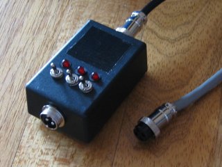 My basic 'controller'. The duct tape covers some extra holes I made for the addition of extra heaters in the future. | 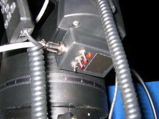 The controller mounted under the LX90's fork arm. It's attached with a couple of strips of velcro. |
An even flashier, yet not all too complicated, circuit would be to use some push-buttons and a binary counter chip to control the heater elements. A 7-segment LCD display would be a simple addition to such a circuit. Depending on the current requirements, you're likely to need to use a relay to do the actual switching.
![]()
![]()
![]()
![]()